Friday, April 21, 2017
Tuesday, April 4, 2017
Spring Break

Solar panel support frame fabrication began with cutting aluminum bar stock down to proper lengths. Each half of the support frame consists of (2) 5 feet and (4) 1 foot pieces. Two L-brackets were used at each corner to form a rectangular box frame. Holes were drilled for bolts and nuts to mate L-brackets and aluminum bar stock.


Holes were drilled for bolts and nuts to mate the two box frames together. With the two halves constructed and connected, measurements were made to place the supports that will connect to the two tilting mechanisms. The placement of the ribs were laid out to avoid interfere with supports. Holes were drilled on the sides of the frames, ribs, and clamps. Adjustments were made to ensure there was enough room to slide the solar panel between the ribs and clamp.
Acrylic panels were purchase to fabricate a box to house the charging components. These pieces will need to be cut down to dimension and bolted together. With the box fabricated and sliders attached to the box, the position and placement can be determined to make connections onto the solar panel frame.
Monday, March 13, 2017
Week 6
Procurement:
Hardware for the mate the ribs and clamps on to the rack were purchased. The match die and drill bit were sourced from home. Bolts for to mate the solar racks were also purchased. The hinges for the acrylic box were purchased. The next step for fabrication is cut the aluminum stock down to size for the sides of the rack along with the supporting joints. Once down to size, the aluminum stock will be drilled and tapped.
Fabrication:
Several more of the 6 cell batteries were downsized to 4 cells.
Testing:
The newly modified 4 cell batteries were tested over the weekend. Several discharge and recharge cycles were placed on the batteries. It was determined with approximated 60 watts and 1 amp output from the solar panels, a battery would be fully charged with 5.86 volts and 2222 mAh energy capacity under a hour.


Thursday, March 9, 2017
Spring Presentation 1
Linked below is Spring Presentation 1
https://drive.google.com/open?id=1XbALC-musVUjFedPGE3YJ-2cIch5JSCKi_EbQAWdOwY
https://drive.google.com/open?id=1XbALC-musVUjFedPGE3YJ-2cIch5JSCKi_EbQAWdOwY
Monday, March 6, 2017
Week 5
It was decided to reduce the batteries from 6 cells to 4 cells in order to drop the voltage. This would allow the motors powering the bogie to be ran directly off the batteries without requiring a buck converter. Modifications were made to prototype a 4 cell battery from a 6 cell battery. This battery was tested to be capable of powering the Arduino, sensors, and motors. Before retrofitting more 4 cell batteries, I tested this prototype battery over the weekend to ensure charging components are compatible. The weather this weekend was terrible with random showers throughout both days. A brief window of direct sunlight allowed me to charge the battery to roughly 15 minutes.

Over the weekend, the connectors for the batteries and associated components arrived. Heat shrink wrap for additional battery modifications were purchased. I can begin making modifications to all the batteries and associated connections.
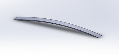
The manufacturing team created a prototype of the overlaying rib. This design of the rib will allow the rib to bolted down along with a clamp instead of needing to weld. The fitment of the rib was tested with the solar panel clamped onto the rib. The edge of the solar panel needs to rest on the rib without any overlap passed the bend of the rib.


Over the weekend, the connectors for the batteries and associated components arrived. Heat shrink wrap for additional battery modifications were purchased. I can begin making modifications to all the batteries and associated connections.
The manufacturing team created a prototype of the overlaying rib. This design of the rib will allow the rib to bolted down along with a clamp instead of needing to weld. The fitment of the rib was tested with the solar panel clamped onto the rib. The edge of the solar panel needs to rest on the rib without any overlap passed the bend of the rib.

Wednesday, March 1, 2017
Week 4
Solar Racking Design:
New changes were made after last week's discussion. The track team expressed doubts of welding. In order to alleviate any extra burden on welding the solar racks, the design was changed so that the ribs could be bolted into place. This new idea was explored with the manufacturing team as the ribs will be produced by Kevin.

A clamp created to sandwich the solar panel between the clamp and ribs. The clamp are adjustable and uses the same hardware to bolt down the ribs onto the rack. Rubber inserts will be placed between the clamp and solar panel to prevent damages while promoting clamping force.

There are still a few minor tweaks that will be needed implemented to finalize the Solidwork design. The design should be completed this week.
Procurement:
A new connector for the modified 4 cell batteries were decided with the Controls team. 11 sets of connectors were order for bogies, charging modules, and batteries. The new 4 cell batteries will need to be shrink wrapped. Proper sized shrink wrap will be purchased locally.
Wednesday, February 22, 2017
Week 3
Design:
With the design approval, calculations of required amount of materials were established. The quantities of aluminum stock was communicated with the track team. Currently, waiting for a response to determine if more material needs to be purchased from Coastal Aluminum. Confirmed with the track improvement team that the ribs will need to be fabricated according to previously mentioned specifications. Measurement of charging components and supporting hinged box were made to create a Solidwork design. The solar rack design still needs minor improvements to the mating of the two separate pieces before completion.
Procurement/Fabrication:
Position locking draw slider was purchased to match the physical dimensions of the solar rack and charging components. I am hoping to have all designs finalized by the first presentation. With that part complete, fabrication of components can begin that weekend.
T-bar:
A new idea of the modifying the supports proposed to the track team. An additional clamping plate between the T-bar and the 3-bar linkage can shift of the weight of the rack further in towards the center or outer perimeter of track loop to help with any stability issues.
Wednesday, February 15, 2017
Week 2
Derick:
Over the weekend, I was able to charge a battery to its maximum capacity. The maximum voltage was 8.60 V. Voltage peaked and any additional further charging did not provide a noticeable voltage increase. The same problem occurred when sunlight was blocked or interrupted for a short duration. The problem was identified to be the charger and its lack of a self-resetting algorithm. Other compatible chargers with a function to reset itself can used to remedy this problem. With a short deadline, this issue will be low priority.
Further design with the racking system incorporated the two T-bar pole mounts. Modifications were made to the rack that includes attachment points to the two T-bar mounts. The four existing T-bar for the pair of solar racks will require adjustment slots in order to compensate for the play made possible from the swaying of the poles or uneven pavement surface. The attachment points on the solar rack lack the dimensions necessary to compensate for the play, therefore the four T-bars was determined to be modified.
A design for a box to store the charging components was created. The basis of this design is to be able to slide a folding box from underneath the charging rack and provide access to the components regardless of the tilt rotation of the solar rack. The tilt rotation of the solar rack is fixed when placed on to the two support poles. With the solar rack removed and spun around in 180 degrees, the rack will be able to tilt in the opposite rotation. The design will provide easy accessible to the components regardless of the orientation of the tilt of the solar rack.
Tuesday, February 7, 2017
Battery Charging
Derick:
This week consisted of me testing the charging operations of the components. The goals of this week were to determine functionality and approximate charging time. The charging components are operational and able to charging a battery from 7.56 V to 8.10 V. Without any references, the state of charge of the battery via voltage readings could not be determined. Time was also immeasurable due to charger resets when input voltage was not within range. Testing of the components will continue next week with a recording device and longer duration in order to determine the maximum voltage.
Parts of the solar rack were dimension-ed and drawn in SolidWorks. After further thought, the solar rack will be redesigned as a single part instead an assembly.
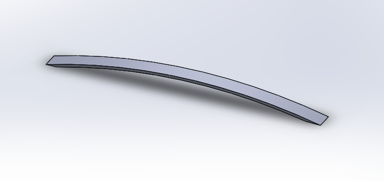
Solar racking rib

Aluminum bar to form rectangular base
Alan:
As stated above, this week was focus on making sure all the components work properly, that they are wired correctly, and testing the whole circuit in the sunlight. Both solar panels will be utilized because we need them to charge one battery pack each. I communicated with the Controls team to make sure which battery packs they will use and they decided to use the 4AA pack.
Two solar are going to be used because charging multiple batteries with one solar panel would not work well. It is possible to connect batteries in parallel in order for one solar panel to charge multiple battery packs but the issue with this is that all the batteries need to have the same voltage, otherwise the battery pack with highest voltage will discharge into the lower voltage one. This is not ideal because the battery packs will not always have the same voltage.
Subscribe to:
Posts (Atom)